Vehicle Control Unit 0.01
This is the c library for controlling the car.
Loading...
Searching...
No Matches
Functions | Variables
main.c File Reference

: Main program body More...

#include "main.h"
#include "cmsis_os.h"
#include "../Inc/Files/can1_dbc.h"
#include "../Inc/Scheduler/Scheduler.h"
#include "../Inc/Sensors/AnalogSensor.h"
#include "../Inc/Systems/Comms/Can/Can.h"
#include "../Inc/Systems/Controller/Apps.h"
#include "../Inc/Systems/Controller/BrakeSystemControl.h"
#include "../Inc/Systems/Controller/RTD.h"
#include "../Inc/Systems/Controller/TorqueControl.h"
#include "../Inc/Systems/External/Inverter.h"
#include "../Inc/Systems/Monitor/AppsMonitor.h"
#include "../Inc/Systems/Monitor/BrakePolice.h"
#include "../Inc/Systems/Monitor/RTDMonitor.h"
#include "../Inc/Systems/Monitor/TorquePolice.h"
#include "../Inc/Utils/Constants.h"
#include "../Inc/Utils/Telemetry.h"
#include "stm32f7xx_hal_adc.h"
#include "stm32f7xx_it.h"
Include dependency graph for main.c:

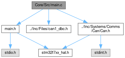
Go to the source code of this file.

Functions

void SystemClock_Config (void)
 System Clock Configuration. More...
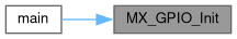
 
static void MX_GPIO_Init (void)
 GPIO Initialization Function. More...
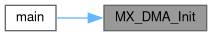
 
static void MX_DMA_Init (void)
 
static void MX_TIM1_Init (void)
 TIM1 Initialization Function. More...
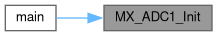
 
static void MX_ADC1_Init (void)
 ADC1 Initialization Function. More...
 
static void MX_ADC2_Init (void)
 ADC2 Initialization Function. More...
 
static void MX_ADC3_Init (void)
 ADC3 Initialization Function. More...
 
static void MX_CAN1_Init (void)
 CAN1 Initialization Function. More...
 
static void MX_CAN2_Init (void)
 CAN2 Initialization Function. More...
 
static void MX_USART3_UART_Init (void)
 USART3 Initialization Function. More...
 
static void MX_TIM2_Init (void)
 TIM2 Initialization Function. More...
 
static void MX_DAC_Init (void)
 DAC Initialization Function. More...
 
static void MX_CAN3_Init (void)
 CAN3 Initialization Function. More...
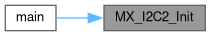
 
static void MX_I2C2_Init (void)
 I2C2 Initialization Function. More...
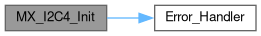
 
static void MX_I2C4_Init (void)
 I2C4 Initialization Function. More...
 
static void MX_SPI4_Init (void)
 SPI4 Initialization Function. More...
 
static void MX_SPI6_Init (void)
 SPI6 Initialization Function. More...
 
void StartDefaultTask (void *argument)
 Function implementing the defaultTask thread. More...
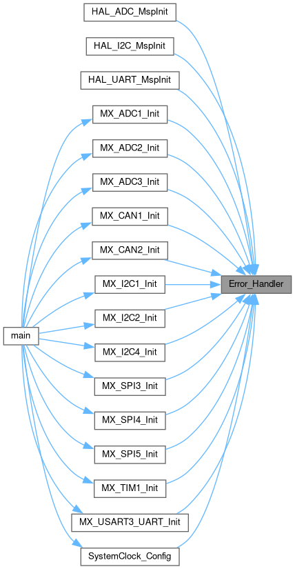
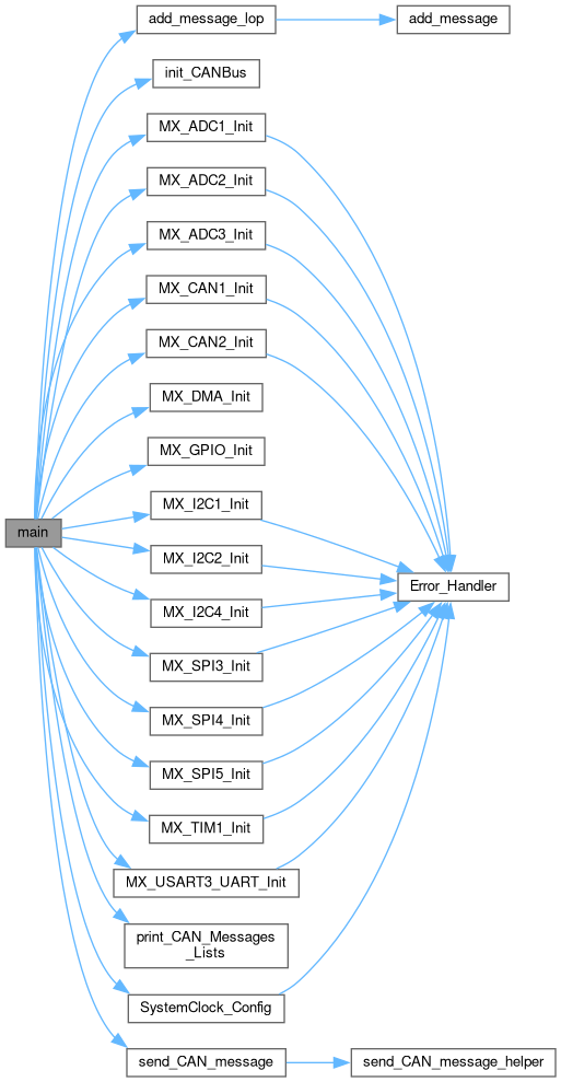
 
int main (void)
 The application entry point. More...
 
int _write (int file, char *data, int len)
 
void vApplicationMallocFailedHook (void)
 
void vApplicationIdleHook (void)
 
void vApplicationStackOverflowHook (TaskHandle_t xTask, char *pcTaskName)
 
void vApplicationTickHook (void)
 
void Error_Handler (void)
 This function is executed in case of error occurrence. More...
 

Variables

ADC_HandleTypeDef hadc1
 
ADC_HandleTypeDef hadc2
 
ADC_HandleTypeDef hadc3
 
DMA_HandleTypeDef hdma_adc1
 
DMA_HandleTypeDef hdma_adc2
 
DMA_HandleTypeDef hdma_adc3
 
CAN_HandleTypeDef hcan1
 
CAN_HandleTypeDef hcan2
 
CAN_HandleTypeDef hcan3
 
DAC_HandleTypeDef hdac
 
DMA_HandleTypeDef hdma_dac1
 
DMA_HandleTypeDef hdma_dac2
 
I2C_HandleTypeDef hi2c2
 
I2C_HandleTypeDef hi2c4
 
SPI_HandleTypeDef hspi4
 
SPI_HandleTypeDef hspi6
 
TIM_HandleTypeDef htim1
 
TIM_HandleTypeDef htim2
 
UART_HandleTypeDef huart3
 
osThreadId_t defaultTaskHandle
 
const osThreadAttr_t defaultTask_attributes
 
uint32_t adc1_buffer [ADC1_CHANNEL_SIZE]
 
uint32_t adc2_buffer [ADC2_CHANNEL_SIZE]
 
uint32_t adc3_buffer [ADC3_CHANNEL_SIZE]
 
uint32_t dac1_buffer [DAC1_BUFFER_SIZE]
 
uint32_t dac2_buffer [DAC2_BUFFER_SIZE]
 
uint8_t digital_out_buffer [NUM_DIGITAL_OUTPUTS]
 
uint8_t digital_in_buffer [NUM_DIGITAL_INPUTS]
 

Detailed Description

: Main program body

Attention

Copyright (c) 2024 STMicroelectronics. All rights reserved.

This software is licensed under terms that can be found in the LICENSE file in the root directory of this software component. If no LICENSE file comes with this software, it is provided AS-IS.

Definition in file main.c.

Function Documentation

◆ _write()

int _write ( int  file,
char *  data,
int  len 
)

Definition at line 1476 of file main.c.

1477{
1478 // Transmit data using USART3
1479 HAL_UART_Transmit(&huart3, (uint8_t *)data, len, HAL_MAX_DELAY);
1480 return len;
1481
1482#endif // <--- DONT DELETE THIS, IT IS LINKED TO LAST LINE IN MAIN FUNCTION TO ALLOW SIL BUILDS
1483
1484}
UART_HandleTypeDef huart3
Definition: main.c:87

◆ Error_Handler()

void Error_Handler ( void  )

This function is executed in case of error occurrence.

Return values
None

Definition at line 1530 of file main.c.

1531{
1532 /* USER CODE BEGIN Error_Handler_Debug */
1533 /* User can add his own implementation to report the HAL error return state */
1534
1535 #ifndef TEST_MODE
1536 __disable_irq();
1537 #endif
1538
1539 while (1)
1540 {
1541 //printf("Error_Handler\r\n");
1542 }
1543 /* USER CODE END Error_Handler_Debug */
1544}
Here is the caller graph for this function:

◆ main()

int main ( void  )

The application entry point.

Return values
int

Definition at line 139 of file main.c.

140{
141
142 /* USER CODE BEGIN 1 */
143
144 #ifndef TEST_MODE
145
146 /* USER CODE END 1 */
147
148 /* MCU Configuration--------------------------------------------------------*/
149
150 /* Reset of all peripherals, Initializes the Flash interface and the Systick. */
151 HAL_Init();
152
153 /* USER CODE BEGIN Init */
154
155 /* USER CODE END Init */
156
157 /* Configure the system clock */
159
160 /* USER CODE BEGIN SysInit */
161
162 /* USER CODE END SysInit */
163
164 /* Initialize all configured peripherals */
165 MX_GPIO_Init();
166 MX_DMA_Init();
167 MX_TIM1_Init();
168 MX_ADC1_Init();
169 MX_ADC2_Init();
170 MX_ADC3_Init();
171 MX_CAN1_Init();
172 MX_CAN2_Init();
174 MX_TIM2_Init();
175 MX_DAC_Init();
176 MX_CAN3_Init();
177 MX_I2C2_Init();
178 MX_I2C4_Init();
179 MX_SPI4_Init();
180 MX_SPI6_Init();
181 /* USER CODE BEGIN 2 */
182
183 // Clear the screen
184 // //printf("\033[2J\033[1;1H");
185 // //printf("Welcome to VCU!!!\r\n");
186 if (init_CANBus(CAN_1) != 0) {
187 // //printf("CAN1 init failed\r\n");
188 }
189
190 // Init Telemetry
192
193 // Begin ADC DMA
194 if(HAL_ADC_Start_DMA(&hadc1, (uint32_t*)adc1_buffer, 7) != HAL_OK) {
196 }
197
198 if(HAL_ADC_Start_DMA(&hadc2, (uint32_t*)adc2_buffer, 7) != HAL_OK) {
200 }
201
202 if(HAL_ADC_Start_DMA(&hadc3, (uint32_t*)adc3_buffer, 8) != HAL_OK) {
204 }
205
206 // Begin DAC DMA
207 if(HAL_DAC_Start_DMA(&hdac, DAC_CHANNEL_1, (uint32_t*)dac1_buffer, DAC1_BUFFER_SIZE, DAC_ALIGN_12B_R) != HAL_OK) {
209 }
210
211 __HAL_UART_ENABLE_IT(&huart3, UART_IT_RXNE);
213
214 uint32_t multi_mode = (ADC123_COMMON->CCR & ADC_CCR_MULTI);
215 //printf("ADC Multi-mode: 0x%08lX\r\n", multi_mode);
216
217 #endif
218
219 // Add a message to the CAN message list
221 { .name = "VDD", .start_bit = 0, .length = 8, .endian = 0, .isSigned = 0, .scale = 0.1, .offset = 0, .min = 0, .max = 255, .unit = "voltage", .reciever = "reciever" },
222 { .name = "Char 2", .start_bit = 8, .length = 8, .endian = 0, .isSigned = 0, .scale = 1, .offset = 0, .min = 0, .max = 255, .unit = "unit", .reciever = "reciever" },
223 { .name = "Char 3", .start_bit = 16, .length = 8, .endian = 0, .isSigned = 0, .scale = 1, .offset = 0, .min = 0, .max = 255, .unit = "unit", .reciever = "reciever" },
224 { .name = "Char 4", .start_bit = 24, .length = 8, .endian = 0, .isSigned = 0, .scale = 1, .offset = 0, .min = 0, .max = 255, .unit = "unit", .reciever = "reciever" },
225 { .name = "Char 5", .start_bit = 32, .length = 8, .endian = 0, .isSigned = 0, .scale = 1, .offset = 0, .min = 0, .max = 255, .unit = "unit", .reciever = "reciever" },
226 { .name = "Char 6", .start_bit = 40, .length = 8, .endian = 0, .isSigned = 0, .scale = 1, .offset = 0, .min = 0, .max = 255, .unit = "unit", .reciever = "reciever" },
227 { .name = "Char 7", .start_bit = 48, .length = 8, .endian = 0, .isSigned = 0, .scale = 1, .offset = 0, .min = 0, .max = 255, .unit = "unit", .reciever = "reciever" },
228 { .name = "Char 8", .start_bit = 56, .length = 8, .endian = 0, .isSigned = 0, .scale = 1, .offset = 0, .min = 0, .max = 255, .unit = "unit", .reciever = "reciever" }
229 };
230
231 add_message_lop(CAN_1, 0x123, 8, 0, 0, "Message 1", "AD3", 8, signals);
232
233
234 add_message_lop(CAN_1, 0x124, 8, 0, 0, "Message 2", "VCU", 8, signals);
235
236 // Print the CAN message list
238
239 uint8_t txdata[8] = {0, 1, 2, 3, 4, 5, 6, 7};
240 send_CAN_message(CAN_1, CAN_2A, 124, txdata, 8);
241
242 // Make Apps Controller and Monitor
243 Apps apps;
244 initApps(&apps, 10, 8, 4);
245
246 AppsMonitor am;
247 initAppsMonitor(&am, &apps, 10);
248
249 // Bind Appsmonitor to Apps
250 apps.base.addMonitor(&apps, &am);
251
252 // Start the Apps Monitor
253 startAppsMonitor(&am);
254
255 // Make Break Controller and Monitor
257 initBrakeSystemControl(&bsc, 10, 200, 400, 1000, 10, 5, 6, 0);
258
259 BrakePolice bp;
260 initBrakePolice(&bp, &bsc, 100, 200);
261
262 // Bind BrakePolice to BrakeSystemControl
263 bsc.base.addMonitor(&bsc, &bp);
264
265 // Start the Brake Controller and Monitor
267 startBrakePolice(&bp);
268
269 // Make RTD Controller and Monitor
270 RTD rtd;
271 initRTD(&rtd, &apps, &bsc, 10, 0, 1);
272
273 RTDMonitor rm;
274 initRTDMonitor(&rm, &rtd, 10);
275
276 // Bind RTDMonitor to RTD
277 rtd.base.addMonitor(&rtd, &rm);
278
279 // Start the RTD Controller and Monitor
280 startRTD(&rtd);
281 startRTDMonitor(&rm);
282
283 // Make Torque Controller and Monitor
284 TorqueControl tc;
285 initTorqueControl(&tc, &apps, 10, 240);
286
287 TorquePolice tp;
288 initTorquePolice(&tp, &tc, &bsc, &rtd, 100, 240);
289
290 // Bind TorquePolice to TorqueControl
291 tc.base.addMonitor(&tc, &tp);
292
293 // Start the Torque Controller and Monitor
296
297 // Make Inverter
298 Inverter inverter;
299 initInverter(&inverter, &tc, 10, 200, 100, 400);
300
301 // Make Scheduler from updateable array
302 Scheduler scheduler;
303
304 Updateable* updateables[6];
305 updateables[0] = &apps.base.system.updateable;
306 updateables[1] = &bsc.base.system.updateable;
307 updateables[2] = &rtd.base.system.updateable;
308 updateables[3] = &tc.base.system.updateable;
309 updateables[4] = &inverter.base.system.updateable;
310 updateables[5] = NULL;
311
312 SchedulerInit(&scheduler, updateables);
313
314 //printf("Starting Vehicle Control Unit with FreeRTOS scheduler...\n");
315
316 // Start the Scheduler
317 SchedulerRun(&scheduler);
318 /* USER CODE END 2 */
319
320 /* Init scheduler */
321 osKernelInitialize();
322
323 /* USER CODE BEGIN RTOS_MUTEX */
324 /* add mutexes, ... */
325 /* USER CODE END RTOS_MUTEX */
326
327 /* USER CODE BEGIN RTOS_SEMAPHORES */
328 /* add semaphores, ... */
329 /* USER CODE END RTOS_SEMAPHORES */
330
331 /* USER CODE BEGIN RTOS_TIMERS */
332 /* start timers, add new ones, ... */
333 /* USER CODE END RTOS_TIMERS */
334
335 /* USER CODE BEGIN RTOS_QUEUES */
336 /* add queues, ... */
337 /* USER CODE END RTOS_QUEUES */
338
339 /* Create the thread(s) */
340 /* creation of defaultTask */
342
343 /* USER CODE BEGIN RTOS_THREADS */
344 /* add threads, ... */
345 /* USER CODE END RTOS_THREADS */
346
347 /* USER CODE BEGIN RTOS_EVENTS */
348 /* add events, ... */
349 /* USER CODE END RTOS_EVENTS */
350
351 /* Start scheduler */
352 osKernelStart();
353
354 /* We should never get here as control is now taken by the scheduler */
355
356 /* Infinite loop */
357 /* USER CODE BEGIN WHILE */
358 static uint32_t test_can_counter = 0;
359 while (1)
360 {
361 //printf("ERROR: Scheduler returned unexpectedly!\n");
362
363 // Send test CAN message every 5 seconds
364 test_can_counter++;
365 if (test_can_counter >= 5) {
366 test_can_counter = 0;
367
368 // Send test CAN message with incrementing data
369 uint8_t test_data[8] = {0xAA, 0xBB, 0xCC, 0xDD, (uint8_t)(HAL_GetTick() & 0xFF), 0x55, 0x66, 0x77};
370 send_CAN_message(CAN_1, CAN_2A, 0x123, test_data, 8);
371
372 // Send another test message with different ID
373 uint8_t test_data2[8] = {0x11, 0x22, 0x33, 0x44, 0x55, 0x66, 0x77, (uint8_t)((HAL_GetTick() >> 8) & 0xFF)};
374 send_CAN_message(CAN_1, CAN_2A, 0x456, test_data2, 8);
375 }
376
377 HAL_Delay(1000);
378 /* USER CODE END WHILE */
379
380 /* USER CODE BEGIN 3 */
381 }
382 #ifndef TEST_MODE
383 /* USER CODE END 3 */
384}
void initAppsMonitor(AppsMonitor *am, Apps *apps, int hz)
Definition: AppsMonitor.c:7
int startAppsMonitor(AppsMonitor *am)
Definition: AppsMonitor.c:14
void initApps(Apps *apps, int hz, int channel1, int channel2)
Initializes the APPs with the given frequency and channel.
Definition: Apps.c:8
int startBrakePolice(BrakePolice *bp)
Definition: BrakePolice.c:13
void initBrakePolice(BrakePolice *bp, BrakeSystemControl *bsc, int hz, int maxTemp)
Definition: BrakePolice.c:5
void initBrakeSystemControl(BrakeSystemControl *bsc, int hz, int maxTemp, int brakeLightActivationPoint, int heavyBrakingActivationPoint, int fbp_channel, int rbp_channel, int temp_channel, int light_port)
Initializes the Braking System with initial settings.
int startBrakeSystemControl(BrakeSystemControl *bsc)
Starts the Brake System Controller.
int init_CANBus(CANBus bus)
Initializes the CANBus struct.
Definition: Can.c:18
@ CAN_1
Definition: Can.h:99
int add_message_lop(CANBus bus, int id, int dlc, int ide, int rtr, const char *name, const char *sender, int signal_count, CAN_Signal_Template *signals)
Adds a message to the CAN message list by passing in the individual message parameters hence "LOP" (L...
Definition: Can.c:56
int send_CAN_message(CANBus bus, CANProtocol protocol, uint32_t id, uint8_t *data, uint8_t len)
Sends a CAN message.
Definition: Can.c:80
@ CAN_2A
Definition: Can.h:105
void print_CAN_Messages_Lists()
Prints the CAN message list.
Definition: Can.c:202
#define DAC1_BUFFER_SIZE
Definition: Constants.h:9
void initInverter(Inverter *inverter, TorqueControl *tc, int hz, int maxCurrent, int maxTemp, int maxVoltage)
Initializes the Inverter with initial settings.
Definition: Inverter.c:6
void initRTDMonitor(RTDMonitor *rtdm, RTD *rtd, int hz)
Initializes the RTD Monitor with initial settings.
Definition: RTDMonitor.c:4
int startRTDMonitor(RTDMonitor *rtdm)
Starts the RTD Monitor.
Definition: RTDMonitor.c:9
int startRTD(RTD *rtd)
Starts the RTD Actuator.
Definition: RTD.c:23
void initRTD(RTD *rtd, Apps *apps, BrakeSystemControl *bsc, int hz, int buttonPort, int piezoPort)
Initializes the RTD Actuator with initial settings.
Definition: RTD.c:6
void SchedulerInit(Scheduler *scheduler, Updateable *updatableArray[])
Definition: Scheduler.c:80
void SchedulerRun(Scheduler *scheduler)
Definition: Scheduler.c:142
static void MX_CAN3_Init(void)
CAN3 Initialization Function.
Definition: main.c:897
void Error_Handler(void)
This function is executed in case of error occurrence.
Definition: main.c:1530
uint32_t adc3_buffer[ADC3_CHANNEL_SIZE]
Definition: main.c:127
static void MX_USART3_UART_Init(void)
USART3 Initialization Function.
Definition: main.c:1251
static void MX_TIM1_Init(void)
TIM1 Initialization Function.
Definition: main.c:1157
ADC_HandleTypeDef hadc1
Definition: main.c:63
const osThreadAttr_t defaultTask_attributes
Definition: main.c:91
static void MX_CAN1_Init(void)
CAN1 Initialization Function.
Definition: main.c:767
DAC_HandleTypeDef hdac
Definition: main.c:74
static void MX_ADC2_Init(void)
ADC2 Initialization Function.
Definition: main.c:546
static void MX_SPI6_Init(void)
SPI6 Initialization Function.
Definition: main.c:1117
static void MX_DMA_Init(void)
Definition: main.c:1284
uint32_t adc2_buffer[ADC2_CHANNEL_SIZE]
Definition: main.c:126
osThreadId_t defaultTaskHandle
Definition: main.c:90
void SystemClock_Config(void)
System Clock Configuration.
Definition: main.c:390
static void MX_CAN2_Init(void)
CAN2 Initialization Function.
Definition: main.c:832
ADC_HandleTypeDef hadc3
Definition: main.c:65
void StartDefaultTask(void *argument)
Function implementing the defaultTask thread.
Definition: main.c:1515
static void MX_ADC1_Init(void)
ADC1 Initialization Function.
Definition: main.c:441
ADC_HandleTypeDef hadc2
Definition: main.c:64
static void MX_ADC3_Init(void)
ADC3 Initialization Function.
Definition: main.c:652
static void MX_SPI4_Init(void)
SPI4 Initialization Function.
Definition: main.c:1077
static void MX_GPIO_Init(void)
GPIO Initialization Function.
Definition: main.c:1315
static void MX_DAC_Init(void)
DAC Initialization Function.
Definition: main.c:934
static void MX_I2C4_Init(void)
I2C4 Initialization Function.
Definition: main.c:1029
static void MX_I2C2_Init(void)
I2C2 Initialization Function.
Definition: main.c:981
uint32_t adc1_buffer[ADC1_CHANNEL_SIZE]
Definition: main.c:125
static void MX_TIM2_Init(void)
TIM2 Initialization Function.
Definition: main.c:1204
uint32_t dac1_buffer[DAC1_BUFFER_SIZE]
Definition: main.c:128
static TelemetrySignal signals[MAX_TELEMETRY_SIGNALS]
Definition: Telemetry.c:8
void initTelemetry(void)
Definition: Telemetry.c:12
int startTorqueControl(TorqueControl *tc)
Starts the Torque Control Actuator.
Definition: TorqueControl.c:13
void initTorqueControl(TorqueControl *tc, Apps *apps, int hz, float maxTorque)
Initializes the Torque Control Actuator with initial settings.
Definition: TorqueControl.c:6
void initTorquePolice(TorquePolice *tp, TorqueControl *tc, BrakeSystemControl *bsc, RTD *rtd, int hz, float maxTorque)
Definition: TorquePolice.c:5
int startTorquePolice(TorquePolice *tp)
Definition: TorquePolice.c:15
void initUartConfigListener(void)
Definition: stm32f7xx_it.c:336
Definition: Apps.h:22
ControllerSystem base
Definition: Apps.h:23
ControllerSystem base
int(* addMonitor)(struct ControllerSystem *controller, MonitorSystem *monitor)
ExternalSystem base
Definition: Inverter.h:9
Definition: RTD.h:11
ControllerSystem base
Definition: RTD.h:12
Updateable updateable
Definition: System.h:18
char name[32]
Definition: Telemetry.h:18
ControllerSystem base
Definition: TorqueControl.h:19
Here is the call graph for this function:

◆ MX_ADC1_Init()

static void MX_ADC1_Init ( void  )
static

ADC1 Initialization Function.

Parameters
None
Return values
None

Configure the global features of the ADC (Clock, Resolution, Data Alignment and number of conversion)

Configure for the selected ADC regular channel its corresponding rank in the sequencer and its sample time.

Configure for the selected ADC regular channel its corresponding rank in the sequencer and its sample time.

Configure for the selected ADC regular channel its corresponding rank in the sequencer and its sample time.

Configure for the selected ADC regular channel its corresponding rank in the sequencer and its sample time.

Configure for the selected ADC regular channel its corresponding rank in the sequencer and its sample time.

Configure for the selected ADC regular channel its corresponding rank in the sequencer and its sample time.

Configure for the selected ADC regular channel its corresponding rank in the sequencer and its sample time.

Definition at line 441 of file main.c.

442{
443
444 /* USER CODE BEGIN ADC1_Init 0 */
445
446 /* USER CODE END ADC1_Init 0 */
447
448 ADC_ChannelConfTypeDef sConfig = {0};
449
450 /* USER CODE BEGIN ADC1_Init 1 */
451
452 /* USER CODE END ADC1_Init 1 */
453
456 hadc1.Instance = ADC1;
457 hadc1.Init.ClockPrescaler = ADC_CLOCK_SYNC_PCLK_DIV4;
458 hadc1.Init.Resolution = ADC_RESOLUTION_12B;
459 hadc1.Init.ScanConvMode = ADC_SCAN_ENABLE;
460 hadc1.Init.ContinuousConvMode = DISABLE;
461 hadc1.Init.DiscontinuousConvMode = DISABLE;
462 hadc1.Init.ExternalTrigConvEdge = ADC_EXTERNALTRIGCONVEDGE_RISING;
463 hadc1.Init.ExternalTrigConv = ADC_EXTERNALTRIGCONV_T2_TRGO;
464 hadc1.Init.DataAlign = ADC_DATAALIGN_RIGHT;
465 hadc1.Init.NbrOfConversion = 7;
466 hadc1.Init.DMAContinuousRequests = ENABLE;
467 hadc1.Init.EOCSelection = ADC_EOC_SEQ_CONV;
468 if (HAL_ADC_Init(&hadc1) != HAL_OK)
469 {
471 }
472
475 sConfig.Channel = ADC_CHANNEL_0;
476 sConfig.Rank = ADC_REGULAR_RANK_1;
477 sConfig.SamplingTime = ADC_SAMPLETIME_28CYCLES;
478 if (HAL_ADC_ConfigChannel(&hadc1, &sConfig) != HAL_OK)
479 {
481 }
482
485 sConfig.Channel = ADC_CHANNEL_2;
486 sConfig.Rank = ADC_REGULAR_RANK_2;
487 if (HAL_ADC_ConfigChannel(&hadc1, &sConfig) != HAL_OK)
488 {
490 }
491
494 sConfig.Channel = ADC_CHANNEL_6;
495 sConfig.Rank = ADC_REGULAR_RANK_3;
496 if (HAL_ADC_ConfigChannel(&hadc1, &sConfig) != HAL_OK)
497 {
499 }
500
503 sConfig.Channel = ADC_CHANNEL_8;
504 sConfig.Rank = ADC_REGULAR_RANK_4;
505 if (HAL_ADC_ConfigChannel(&hadc1, &sConfig) != HAL_OK)
506 {
508 }
509
512 sConfig.Channel = ADC_CHANNEL_10;
513 sConfig.Rank = ADC_REGULAR_RANK_5;
514 if (HAL_ADC_ConfigChannel(&hadc1, &sConfig) != HAL_OK)
515 {
517 }
518
521 sConfig.Channel = ADC_CHANNEL_12;
522 sConfig.Rank = ADC_REGULAR_RANK_6;
523 if (HAL_ADC_ConfigChannel(&hadc1, &sConfig) != HAL_OK)
524 {
526 }
527
530 sConfig.Rank = ADC_REGULAR_RANK_7;
531 if (HAL_ADC_ConfigChannel(&hadc1, &sConfig) != HAL_OK)
532 {
534 }
535 /* USER CODE BEGIN ADC1_Init 2 */
536
537 /* USER CODE END ADC1_Init 2 */
538
539}
#define ENABLE(item_)
Definition: Updateable.h:10
#define DISABLE(item_)
Definition: Updateable.h:11
Here is the call graph for this function:
Here is the caller graph for this function:

◆ MX_ADC2_Init()

static void MX_ADC2_Init ( void  )
static

ADC2 Initialization Function.

Parameters
None
Return values
None

Configure the global features of the ADC (Clock, Resolution, Data Alignment and number of conversion)

Configure for the selected ADC regular channel its corresponding rank in the sequencer and its sample time.

Configure for the selected ADC regular channel its corresponding rank in the sequencer and its sample time.

Configure for the selected ADC regular channel its corresponding rank in the sequencer and its sample time.

Configure for the selected ADC regular channel its corresponding rank in the sequencer and its sample time.

Configure for the selected ADC regular channel its corresponding rank in the sequencer and its sample time.

Configure for the selected ADC regular channel its corresponding rank in the sequencer and its sample time.

Configure for the selected ADC regular channel its corresponding rank in the sequencer and its sample time.

Definition at line 546 of file main.c.

547{
548
549 /* USER CODE BEGIN ADC2_Init 0 */
550
551 /* USER CODE END ADC2_Init 0 */
552
553 ADC_ChannelConfTypeDef sConfig = {0};
554
555 /* USER CODE BEGIN ADC2_Init 1 */
556
557 /* USER CODE END ADC2_Init 1 */
558
561 hadc2.Instance = ADC2;
562 hadc2.Init.ClockPrescaler = ADC_CLOCK_SYNC_PCLK_DIV4;
563 hadc2.Init.Resolution = ADC_RESOLUTION_12B;
564 hadc2.Init.ScanConvMode = ADC_SCAN_ENABLE;
565 hadc2.Init.ContinuousConvMode = DISABLE;
566 hadc2.Init.DiscontinuousConvMode = DISABLE;
567 hadc2.Init.ExternalTrigConvEdge = ADC_EXTERNALTRIGCONVEDGE_RISING;
568 hadc2.Init.ExternalTrigConv = ADC_EXTERNALTRIGCONV_T2_TRGO;
569 hadc2.Init.DataAlign = ADC_DATAALIGN_RIGHT;
570 hadc2.Init.NbrOfConversion = 7;
571 hadc2.Init.DMAContinuousRequests = ENABLE;
572 hadc2.Init.EOCSelection = ADC_EOC_SEQ_CONV;
573 if (HAL_ADC_Init(&hadc2) != HAL_OK)
574 {
576 }
577
580 sConfig.Channel = ADC_CHANNEL_1;
581 sConfig.Rank = ADC_REGULAR_RANK_1;
582 sConfig.SamplingTime = ADC_SAMPLETIME_28CYCLES;
583 if (HAL_ADC_ConfigChannel(&hadc2, &sConfig) != HAL_OK)
584 {
586 }
587
590 sConfig.Channel = ADC_CHANNEL_3;
591 sConfig.Rank = ADC_REGULAR_RANK_2;
592 if (HAL_ADC_ConfigChannel(&hadc2, &sConfig) != HAL_OK)
593 {
595 }
596
599 sConfig.Channel = ADC_CHANNEL_7;
600 sConfig.Rank = ADC_REGULAR_RANK_3;
601 if (HAL_ADC_ConfigChannel(&hadc2, &sConfig) != HAL_OK)
602 {
604 }
605
608 sConfig.Channel = ADC_CHANNEL_9;
609 sConfig.Rank = ADC_REGULAR_RANK_4;
610 if (HAL_ADC_ConfigChannel(&hadc2, &sConfig) != HAL_OK)
611 {
613 }
614
617 sConfig.Channel = ADC_CHANNEL_11;
618 sConfig.Rank = ADC_REGULAR_RANK_5;
619 if (HAL_ADC_ConfigChannel(&hadc2, &sConfig) != HAL_OK)
620 {
622 }
623
626 sConfig.Channel = ADC_CHANNEL_13;
627 sConfig.Rank = ADC_REGULAR_RANK_6;
628 if (HAL_ADC_ConfigChannel(&hadc2, &sConfig) != HAL_OK)
629 {
631 }
632
635 sConfig.Channel = ADC_CHANNEL_15;
636 sConfig.Rank = ADC_REGULAR_RANK_7;
637 if (HAL_ADC_ConfigChannel(&hadc2, &sConfig) != HAL_OK)
638 {
640 }
641 /* USER CODE BEGIN ADC2_Init 2 */
642
643 /* USER CODE END ADC2_Init 2 */
644
645}
Here is the call graph for this function:
Here is the caller graph for this function:

◆ MX_ADC3_Init()

static void MX_ADC3_Init ( void  )
static

ADC3 Initialization Function.

Parameters
None
Return values
None

Configure the global features of the ADC (Clock, Resolution, Data Alignment and number of conversion)

Configure for the selected ADC regular channel its corresponding rank in the sequencer and its sample time.

Configure for the selected ADC regular channel its corresponding rank in the sequencer and its sample time.

Configure for the selected ADC regular channel its corresponding rank in the sequencer and its sample time.

Configure for the selected ADC regular channel its corresponding rank in the sequencer and its sample time.

Configure for the selected ADC regular channel its corresponding rank in the sequencer and its sample time.

Configure for the selected ADC regular channel its corresponding rank in the sequencer and its sample time.

Configure for the selected ADC regular channel its corresponding rank in the sequencer and its sample time.

Configure for the selected ADC regular channel its corresponding rank in the sequencer and its sample time.

Definition at line 652 of file main.c.

653{
654
655 /* USER CODE BEGIN ADC3_Init 0 */
656
657 /* USER CODE END ADC3_Init 0 */
658
659 ADC_ChannelConfTypeDef sConfig = {0};
660
661 /* USER CODE BEGIN ADC3_Init 1 */
662
663 /* USER CODE END ADC3_Init 1 */
664
667 hadc3.Instance = ADC3;
668 hadc3.Init.ClockPrescaler = ADC_CLOCK_SYNC_PCLK_DIV4;
669 hadc3.Init.Resolution = ADC_RESOLUTION_12B;
670 hadc3.Init.ScanConvMode = ADC_SCAN_ENABLE;
671 hadc3.Init.ContinuousConvMode = DISABLE;
672 hadc3.Init.DiscontinuousConvMode = DISABLE;
673 hadc3.Init.ExternalTrigConvEdge = ADC_EXTERNALTRIGCONVEDGE_RISING;
674 hadc3.Init.ExternalTrigConv = ADC_EXTERNALTRIGCONV_T2_TRGO;
675 hadc3.Init.DataAlign = ADC_DATAALIGN_RIGHT;
676 hadc3.Init.NbrOfConversion = 8;
677 hadc3.Init.DMAContinuousRequests = ENABLE;
678 hadc3.Init.EOCSelection = ADC_EOC_SINGLE_CONV;
679 if (HAL_ADC_Init(&hadc3) != HAL_OK)
680 {
682 }
683
686 sConfig.Channel = ADC_CHANNEL_4;
687 sConfig.Rank = ADC_REGULAR_RANK_1;
688 sConfig.SamplingTime = ADC_SAMPLETIME_28CYCLES;
689 if (HAL_ADC_ConfigChannel(&hadc3, &sConfig) != HAL_OK)
690 {
692 }
693
696 sConfig.Channel = ADC_CHANNEL_5;
697 sConfig.Rank = ADC_REGULAR_RANK_2;
698 if (HAL_ADC_ConfigChannel(&hadc3, &sConfig) != HAL_OK)
699 {
701 }
702
705 sConfig.Channel = ADC_CHANNEL_6;
706 sConfig.Rank = ADC_REGULAR_RANK_3;
707 if (HAL_ADC_ConfigChannel(&hadc3, &sConfig) != HAL_OK)
708 {
710 }
711
714 sConfig.Channel = ADC_CHANNEL_7;
715 sConfig.Rank = ADC_REGULAR_RANK_4;
716 if (HAL_ADC_ConfigChannel(&hadc3, &sConfig) != HAL_OK)
717 {
719 }
720
723 sConfig.Channel = ADC_CHANNEL_8;
724 sConfig.Rank = ADC_REGULAR_RANK_5;
725 if (HAL_ADC_ConfigChannel(&hadc3, &sConfig) != HAL_OK)
726 {
728 }
729
732 sConfig.Channel = ADC_CHANNEL_9;
733 sConfig.Rank = ADC_REGULAR_RANK_6;
734 if (HAL_ADC_ConfigChannel(&hadc3, &sConfig) != HAL_OK)
735 {
737 }
738
741 sConfig.Channel = ADC_CHANNEL_14;
742 sConfig.Rank = ADC_REGULAR_RANK_7;
743 if (HAL_ADC_ConfigChannel(&hadc3, &sConfig) != HAL_OK)
744 {
746 }
747
750 sConfig.Channel = ADC_CHANNEL_15;
751 sConfig.Rank = ADC_REGULAR_RANK_8;
752 if (HAL_ADC_ConfigChannel(&hadc3, &sConfig) != HAL_OK)
753 {
755 }
756 /* USER CODE BEGIN ADC3_Init 2 */
757
758 /* USER CODE END ADC3_Init 2 */
759
760}
Here is the call graph for this function:
Here is the caller graph for this function:

◆ MX_CAN1_Init()

static void MX_CAN1_Init ( void  )
static

CAN1 Initialization Function.

Parameters
None
Return values
None

Definition at line 767 of file main.c.

768{
769
770 /* USER CODE BEGIN CAN1_Init 0 */
771
772 /* USER CODE END CAN1_Init 0 */
773
774 /* USER CODE BEGIN CAN1_Init 1 */
775
776 /* USER CODE END CAN1_Init 1 */
777 hcan1.Instance = CAN1;
778 hcan1.Init.Prescaler = 3;
779 hcan1.Init.Mode = CAN_MODE_NORMAL;
780 hcan1.Init.SyncJumpWidth = CAN_SJW_1TQ;
781 hcan1.Init.TimeSeg1 = CAN_BS1_13TQ;
782 hcan1.Init.TimeSeg2 = CAN_BS2_2TQ;
783 hcan1.Init.TimeTriggeredMode = DISABLE;
784 hcan1.Init.AutoBusOff = DISABLE;
785 hcan1.Init.AutoWakeUp = DISABLE;
786 hcan1.Init.AutoRetransmission = DISABLE;
787 hcan1.Init.ReceiveFifoLocked = DISABLE;
788 hcan1.Init.TransmitFifoPriority = DISABLE;
789 if (HAL_CAN_Init(&hcan1) != HAL_OK)
790 {
792 }
793 /* USER CODE BEGIN CAN1_Init 2 */
794 CAN_FilterTypeDef sFilterConfig;
795 sFilterConfig.FilterBank = 0;
796 sFilterConfig.FilterMode = CAN_FILTERMODE_IDMASK;
797 sFilterConfig.FilterScale = CAN_FILTERSCALE_32BIT;
798 sFilterConfig.FilterIdHigh = 0x0000;
799 sFilterConfig.FilterIdLow = 0x0000;
800 sFilterConfig.FilterMaskIdHigh = 0x0000;
801 sFilterConfig.FilterMaskIdLow = 0x0000;
802 sFilterConfig.FilterFIFOAssignment = CAN_RX_FIFO0;
803 sFilterConfig.FilterActivation = ENABLE;
804 sFilterConfig.SlaveStartFilterBank = 14;
805 HAL_CAN_ConfigFilter(&hcan1, &sFilterConfig);
806
807 // Stop CAN
808 HAL_CAN_Stop(&hcan1);
809 // Start CAN
810 if (HAL_CAN_Start(&hcan1) != HAL_OK) {
811 //printf("CAN1 Start Error: ErrorCode = 0x%lX\r\n", hcan1.ErrorCode);
812 }
813
814 // Start IRQ for CAN Rx
815 if (HAL_CAN_ActivateNotification(&hcan1, CAN_IT_RX_FIFO0_MSG_PENDING) != HAL_OK) {
816 //printf("interrupt CAN1 init failed\r\n");
817 }
818
819 // Enable TX completion interrupts for telemetry
820 if (HAL_CAN_ActivateNotification(&hcan1, CAN_IT_TX_MAILBOX_EMPTY) != HAL_OK) {
821 //printf("CAN1 TX interrupt init failed\r\n");
822 }
823 /* USER CODE END CAN1_Init 2 */
824
825}
CAN_HandleTypeDef hcan1
Definition: main.c:70
Here is the call graph for this function:
Here is the caller graph for this function:

◆ MX_CAN2_Init()

static void MX_CAN2_Init ( void  )
static

CAN2 Initialization Function.

Parameters
None
Return values
None

Definition at line 832 of file main.c.
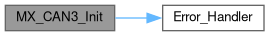
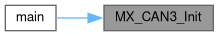
833{
834
835 /* USER CODE BEGIN CAN2_Init 0 */
836
837 /* USER CODE END CAN2_Init 0 */
838
839 /* USER CODE BEGIN CAN2_Init 1 */
840
841 /* USER CODE END CAN2_Init 1 */
842 hcan2.Instance = CAN2;
843 hcan2.Init.Prescaler = 4;
844 hcan2.Init.Mode = CAN_MODE_NORMAL;
845 hcan2.Init.SyncJumpWidth = CAN_SJW_1TQ;
846 hcan2.Init.TimeSeg1 = CAN_BS1_10TQ;
847 hcan2.Init.TimeSeg2 = CAN_BS2_1TQ;
848 hcan2.Init.TimeTriggeredMode = DISABLE;
849 hcan2.Init.AutoBusOff = DISABLE;
850 hcan2.Init.AutoWakeUp = DISABLE;
851 hcan2.Init.AutoRetransmission = DISABLE;
852 hcan2.Init.ReceiveFifoLocked = DISABLE;
853 hcan2.Init.TransmitFifoPriority = DISABLE;
854 if (HAL_CAN_Init(&hcan2) != HAL_OK)
855 {
857 }
858 /* USER CODE BEGIN CAN2_Init 2 */
859 CAN_FilterTypeDef sFilterConfig;
860 sFilterConfig.FilterBank = 0;
861 sFilterConfig.FilterMode = CAN_FILTERMODE_IDMASK;
862 sFilterConfig.FilterScale = CAN_FILTERSCALE_32BIT;
863 sFilterConfig.FilterIdHigh = 0x0000;
864 sFilterConfig.FilterIdLow = 0x0000;
865 sFilterConfig.FilterMaskIdHigh = 0x0000;
866 sFilterConfig.FilterMaskIdLow = 0x0000;
867 sFilterConfig.FilterFIFOAssignment = CAN_RX_FIFO0;
868 sFilterConfig.FilterActivation = ENABLE;
869 sFilterConfig.SlaveStartFilterBank = 14;
870 HAL_CAN_ConfigFilter(&hcan2, &sFilterConfig);
871
872 // Stop CAN
873 HAL_CAN_Stop(&hcan2);
874 // Start CAN
875 if (HAL_CAN_Start(&hcan2) != HAL_OK) {
876 //printf("CAN2 Start Error: ErrorCode = 0x%lX\r\n", hcan2.ErrorCode);
877 }
878
879 // Start IRQ for CAN Rx
880 if (HAL_CAN_ActivateNotification(&hcan2, CAN_IT_RX_FIFO0_MSG_PENDING) != HAL_OK) {
881 //printf("interrupt CAN2 init failed\r\n");
882 }
883
884 // Enable TX completion interrupts for telemetry
885 if (HAL_CAN_ActivateNotification(&hcan2, CAN_IT_TX_MAILBOX_EMPTY) != HAL_OK) {
886 //printf("CAN2 TX interrupt init failed\r\n");
887 }
888 /* USER CODE END CAN2_Init 2 */
889
890}
CAN_HandleTypeDef hcan2
Definition: main.c:71
Here is the call graph for this function:
Here is the caller graph for this function:

◆ MX_CAN3_Init()

static void MX_CAN3_Init ( void  )
static

CAN3 Initialization Function.

Parameters
None
Return values
None

Definition at line 897 of file main.c.
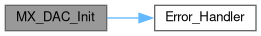
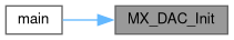
898{
899
900 /* USER CODE BEGIN CAN3_Init 0 */
901
902 /* USER CODE END CAN3_Init 0 */
903
904 /* USER CODE BEGIN CAN3_Init 1 */
905
906 /* USER CODE END CAN3_Init 1 */
907 hcan3.Instance = CAN3;
908 hcan3.Init.Prescaler = 16;
909 hcan3.Init.Mode = CAN_MODE_NORMAL;
910 hcan3.Init.SyncJumpWidth = CAN_SJW_1TQ;
911 hcan3.Init.TimeSeg1 = CAN_BS1_1TQ;
912 hcan3.Init.TimeSeg2 = CAN_BS2_1TQ;
913 hcan3.Init.TimeTriggeredMode = DISABLE;
914 hcan3.Init.AutoBusOff = DISABLE;
915 hcan3.Init.AutoWakeUp = DISABLE;
916 hcan3.Init.AutoRetransmission = DISABLE;
917 hcan3.Init.ReceiveFifoLocked = DISABLE;
918 hcan3.Init.TransmitFifoPriority = DISABLE;
919 if (HAL_CAN_Init(&hcan3) != HAL_OK)
920 {
922 }
923 /* USER CODE BEGIN CAN3_Init 2 */
924
925 /* USER CODE END CAN3_Init 2 */
926
927}
CAN_HandleTypeDef hcan3
Definition: main.c:72
Here is the call graph for this function:
Here is the caller graph for this function:

◆ MX_DAC_Init()

static void MX_DAC_Init ( void  )
static

DAC Initialization Function.

Parameters
None
Return values
None

DAC Initialization

DAC channel OUT1 config

DAC channel OUT2 config

Definition at line 934 of file main.c.

935{
936
937 /* USER CODE BEGIN DAC_Init 0 */
938
939 /* USER CODE END DAC_Init 0 */
940
941 DAC_ChannelConfTypeDef sConfig = {0};
942
943 /* USER CODE BEGIN DAC_Init 1 */
944
945 /* USER CODE END DAC_Init 1 */
946
949 hdac.Instance = DAC;
950 if (HAL_DAC_Init(&hdac) != HAL_OK)
951 {
953 }
954
957 sConfig.DAC_Trigger = DAC_TRIGGER_T2_TRGO;
958 sConfig.DAC_OutputBuffer = DAC_OUTPUTBUFFER_ENABLE;
959 if (HAL_DAC_ConfigChannel(&hdac, &sConfig, DAC_CHANNEL_1) != HAL_OK)
960 {
962 }
963
966 if (HAL_DAC_ConfigChannel(&hdac, &sConfig, DAC_CHANNEL_2) != HAL_OK)
967 {
969 }
970 /* USER CODE BEGIN DAC_Init 2 */
971
972 /* USER CODE END DAC_Init 2 */
973
974}
Here is the call graph for this function:
Here is the caller graph for this function:

◆ MX_DMA_Init()

static void MX_DMA_Init ( void  )
static

Enable DMA controller clock

Definition at line 1284 of file main.c.

1285{
1286
1287 /* DMA controller clock enable */
1288 __HAL_RCC_DMA2_CLK_ENABLE();
1289 __HAL_RCC_DMA1_CLK_ENABLE();
1290
1291 /* DMA interrupt init */
1292 /* DMA1_Stream5_IRQn interrupt configuration */
1293 HAL_NVIC_SetPriority(DMA1_Stream5_IRQn, 5, 0);
1294 HAL_NVIC_EnableIRQ(DMA1_Stream5_IRQn);
1295 /* DMA1_Stream6_IRQn interrupt configuration */
1296 HAL_NVIC_SetPriority(DMA1_Stream6_IRQn, 5, 0);
1297 HAL_NVIC_EnableIRQ(DMA1_Stream6_IRQn);
1298 /* DMA2_Stream0_IRQn interrupt configuration */
1299 HAL_NVIC_SetPriority(DMA2_Stream0_IRQn, 5, 0);
1300 HAL_NVIC_EnableIRQ(DMA2_Stream0_IRQn);
1301 /* DMA2_Stream1_IRQn interrupt configuration */
1302 HAL_NVIC_SetPriority(DMA2_Stream1_IRQn, 5, 0);
1303 HAL_NVIC_EnableIRQ(DMA2_Stream1_IRQn);
1304 /* DMA2_Stream2_IRQn interrupt configuration */
1305 HAL_NVIC_SetPriority(DMA2_Stream2_IRQn, 5, 0);
1306 HAL_NVIC_EnableIRQ(DMA2_Stream2_IRQn);
1307
1308}
Here is the caller graph for this function:

◆ MX_GPIO_Init()

static void MX_GPIO_Init ( void  )
static

GPIO Initialization Function.

Parameters
None
Return values
None

Definition at line 1315 of file main.c.

1316{
1317 GPIO_InitTypeDef GPIO_InitStruct = {0};
1318/* USER CODE BEGIN MX_GPIO_Init_1 */
1319/* USER CODE END MX_GPIO_Init_1 */
1320
1321 /* GPIO Ports Clock Enable */
1322 __HAL_RCC_GPIOE_CLK_ENABLE();
1323 __HAL_RCC_GPIOC_CLK_ENABLE();
1324 __HAL_RCC_GPIOF_CLK_ENABLE();
1325 __HAL_RCC_GPIOH_CLK_ENABLE();
1326 __HAL_RCC_GPIOA_CLK_ENABLE();
1327 __HAL_RCC_GPIOB_CLK_ENABLE();
1328 __HAL_RCC_GPIOG_CLK_ENABLE();
1329 __HAL_RCC_GPIOD_CLK_ENABLE();
1330
1331 /*Configure GPIO pin Output Level */
1332 HAL_GPIO_WritePin(GPIOF, GPIO_PIN_12|GPIO_PIN_13, GPIO_PIN_RESET);
1333
1334 /*Configure GPIO pin Output Level */
1335 HAL_GPIO_WritePin(GPIOE, GPIO_PIN_7|GPIO_PIN_8|GPIO_PIN_9|GPIO_PIN_11
1336 |GPIO_PIN_13, GPIO_PIN_RESET);
1337
1338 /*Configure GPIO pin Output Level */
1339 HAL_GPIO_WritePin(GPIOD, GPIO_PIN_14|GPIO_PIN_15, GPIO_PIN_RESET);
1340
1341 /*Configure GPIO pin Output Level */
1342 HAL_GPIO_WritePin(GPIOG, GPIO_PIN_9, GPIO_PIN_RESET);
1343
1344 /*Configure GPIO pin Output Level */
1345 HAL_GPIO_WritePin(LD2_GPIO_Port, LD2_Pin, GPIO_PIN_RESET);
1346
1347 /*Configure GPIO pins : PE3 PE4 PE10 PE12
1348 PE14 PE15 PE0 PE1 */
1349 GPIO_InitStruct.Pin = GPIO_PIN_3|GPIO_PIN_4|GPIO_PIN_10|GPIO_PIN_12
1350 |GPIO_PIN_14|GPIO_PIN_15|GPIO_PIN_0|GPIO_PIN_1;
1351 GPIO_InitStruct.Mode = GPIO_MODE_ANALOG;
1352 GPIO_InitStruct.Pull = GPIO_NOPULL;
1353 HAL_GPIO_Init(GPIOE, &GPIO_InitStruct);
1354
1355 /*Configure GPIO pin : USER_Btn_Pin */
1356 GPIO_InitStruct.Pin = USER_Btn_Pin;
1357 GPIO_InitStruct.Mode = GPIO_MODE_IT_RISING;
1358 GPIO_InitStruct.Pull = GPIO_NOPULL;
1359 HAL_GPIO_Init(USER_Btn_GPIO_Port, &GPIO_InitStruct);
1360
1361 /*Configure GPIO pins : PF2 PF11 */
1362 GPIO_InitStruct.Pin = GPIO_PIN_2|GPIO_PIN_11;
1363 GPIO_InitStruct.Mode = GPIO_MODE_ANALOG;
1364 GPIO_InitStruct.Pull = GPIO_NOPULL;
1365 HAL_GPIO_Init(GPIOF, &GPIO_InitStruct);
1366
1367 /*Configure GPIO pins : PB2 PB10 PB11 PB12
1368 PB14 PB15 PB4 PB6 */
1369 GPIO_InitStruct.Pin = GPIO_PIN_2|GPIO_PIN_10|GPIO_PIN_11|GPIO_PIN_12
1370 |GPIO_PIN_14|GPIO_PIN_15|GPIO_PIN_4|GPIO_PIN_6;
1371 GPIO_InitStruct.Mode = GPIO_MODE_ANALOG;
1372 GPIO_InitStruct.Pull = GPIO_NOPULL;
1373 HAL_GPIO_Init(GPIOB, &GPIO_InitStruct);
1374
1375 /*Configure GPIO pins : PF12 PF13 */
1376 GPIO_InitStruct.Pin = GPIO_PIN_12|GPIO_PIN_13;
1377 GPIO_InitStruct.Mode = GPIO_MODE_OUTPUT_PP;
1378 GPIO_InitStruct.Pull = GPIO_NOPULL;
1379 GPIO_InitStruct.Speed = GPIO_SPEED_FREQ_LOW;
1380 HAL_GPIO_Init(GPIOF, &GPIO_InitStruct);
1381
1382 /*Configure GPIO pins : PG0 PG1 PG2 PG3
1383 PG4 PG5 PG6 PG8
1384 PG10 PG11 PG15 */
1385 GPIO_InitStruct.Pin = GPIO_PIN_0|GPIO_PIN_1|GPIO_PIN_2|GPIO_PIN_3
1386 |GPIO_PIN_4|GPIO_PIN_5|GPIO_PIN_6|GPIO_PIN_8
1387 |GPIO_PIN_10|GPIO_PIN_11|GPIO_PIN_15;
1388 GPIO_InitStruct.Mode = GPIO_MODE_ANALOG;
1389 GPIO_InitStruct.Pull = GPIO_NOPULL;
1390 HAL_GPIO_Init(GPIOG, &GPIO_InitStruct);
1391
1392 /*Configure GPIO pins : PE7 PE8 PE9 PE11
1393 PE13 */
1394 GPIO_InitStruct.Pin = GPIO_PIN_7|GPIO_PIN_8|GPIO_PIN_9|GPIO_PIN_11
1395 |GPIO_PIN_13;
1396 GPIO_InitStruct.Mode = GPIO_MODE_OUTPUT_PP;
1397 GPIO_InitStruct.Pull = GPIO_NOPULL;
1398 GPIO_InitStruct.Speed = GPIO_SPEED_FREQ_LOW;
1399 HAL_GPIO_Init(GPIOE, &GPIO_InitStruct);
1400
1401 /*Configure GPIO pins : PD10 PD11 PD12 PD13
1402 PD3 PD4 PD5 PD6
1403 PD7 */
1404 GPIO_InitStruct.Pin = GPIO_PIN_10|GPIO_PIN_11|GPIO_PIN_12|GPIO_PIN_13
1405 |GPIO_PIN_3|GPIO_PIN_4|GPIO_PIN_5|GPIO_PIN_6
1406 |GPIO_PIN_7;
1407 GPIO_InitStruct.Mode = GPIO_MODE_ANALOG;
1408 GPIO_InitStruct.Pull = GPIO_NOPULL;
1409 HAL_GPIO_Init(GPIOD, &GPIO_InitStruct);
1410
1411 /*Configure GPIO pins : PD14 PD15 */
1412 GPIO_InitStruct.Pin = GPIO_PIN_14|GPIO_PIN_15;
1413 GPIO_InitStruct.Mode = GPIO_MODE_OUTPUT_PP;
1414 GPIO_InitStruct.Pull = GPIO_NOPULL;
1415 GPIO_InitStruct.Speed = GPIO_SPEED_FREQ_LOW;
1416 HAL_GPIO_Init(GPIOD, &GPIO_InitStruct);
1417
1418 /*Configure GPIO pin : USB_OverCurrent_Pin */
1419 GPIO_InitStruct.Pin = USB_OverCurrent_Pin;
1420 GPIO_InitStruct.Mode = GPIO_MODE_INPUT;
1421 GPIO_InitStruct.Pull = GPIO_NOPULL;
1422 HAL_GPIO_Init(USB_OverCurrent_GPIO_Port, &GPIO_InitStruct);
1423
1424 /*Configure GPIO pins : PC6 PC7 PC8 PC9
1425 PC10 PC11 PC12 */
1426 GPIO_InitStruct.Pin = GPIO_PIN_6|GPIO_PIN_7|GPIO_PIN_8|GPIO_PIN_9
1427 |GPIO_PIN_10|GPIO_PIN_11|GPIO_PIN_12;
1428 GPIO_InitStruct.Mode = GPIO_MODE_AF_PP;
1429 GPIO_InitStruct.Pull = GPIO_NOPULL;
1430 GPIO_InitStruct.Speed = GPIO_SPEED_FREQ_VERY_HIGH;
1431 GPIO_InitStruct.Alternate = GPIO_AF12_SDMMC1;
1432 HAL_GPIO_Init(GPIOC, &GPIO_InitStruct);
1433
1434 /*Configure GPIO pins : PA9 PA10 PA11 PA12 */
1435 GPIO_InitStruct.Pin = GPIO_PIN_9|GPIO_PIN_10|GPIO_PIN_11|GPIO_PIN_12;
1436 GPIO_InitStruct.Mode = GPIO_MODE_ANALOG;
1437 GPIO_InitStruct.Pull = GPIO_NOPULL;
1438 HAL_GPIO_Init(GPIOA, &GPIO_InitStruct);
1439
1440 /*Configure GPIO pin : PD2 */
1441 GPIO_InitStruct.Pin = GPIO_PIN_2;
1442 GPIO_InitStruct.Mode = GPIO_MODE_AF_PP;
1443 GPIO_InitStruct.Pull = GPIO_NOPULL;
1444 GPIO_InitStruct.Speed = GPIO_SPEED_FREQ_VERY_HIGH;
1445 GPIO_InitStruct.Alternate = GPIO_AF12_SDMMC1;
1446 HAL_GPIO_Init(GPIOD, &GPIO_InitStruct);
1447
1448 /*Configure GPIO pin : PG9 */
1449 GPIO_InitStruct.Pin = GPIO_PIN_9;
1450 GPIO_InitStruct.Mode = GPIO_MODE_OUTPUT_PP;
1451 GPIO_InitStruct.Pull = GPIO_NOPULL;
1452 GPIO_InitStruct.Speed = GPIO_SPEED_FREQ_LOW;
1453 HAL_GPIO_Init(GPIOG, &GPIO_InitStruct);
1454
1455 /*Configure GPIO pin : LD2_Pin */
1456 GPIO_InitStruct.Pin = LD2_Pin;
1457 GPIO_InitStruct.Mode = GPIO_MODE_OUTPUT_PP;
1458 GPIO_InitStruct.Pull = GPIO_NOPULL;
1459 GPIO_InitStruct.Speed = GPIO_SPEED_FREQ_LOW;
1460 HAL_GPIO_Init(LD2_GPIO_Port, &GPIO_InitStruct);
1461
1462 /*Configure GPIO pins : PB8 PB9 */
1463 GPIO_InitStruct.Pin = GPIO_PIN_8|GPIO_PIN_9;
1464 GPIO_InitStruct.Mode = GPIO_MODE_AF_PP;
1465 GPIO_InitStruct.Pull = GPIO_NOPULL;
1466 GPIO_InitStruct.Speed = GPIO_SPEED_FREQ_VERY_HIGH;
1467 GPIO_InitStruct.Alternate = GPIO_AF12_SDMMC1;
1468 HAL_GPIO_Init(GPIOB, &GPIO_InitStruct);
1469
1470/* USER CODE BEGIN MX_GPIO_Init_2 */
1471/* USER CODE END MX_GPIO_Init_2 */
1472}
#define USB_OverCurrent_GPIO_Port
Definition: main.h:73
#define LD2_GPIO_Port
Definition: main.h:79
#define USB_OverCurrent_Pin
Definition: main.h:72
#define USER_Btn_Pin
Definition: main.h:64
#define USER_Btn_GPIO_Port
Definition: main.h:65
#define LD2_Pin
Definition: main.h:78
Here is the caller graph for this function:

◆ MX_I2C2_Init()

static void MX_I2C2_Init ( void  )
static

I2C2 Initialization Function.

Parameters
None
Return values
None

Configure Analogue filter

Configure Digital filter

Definition at line 981 of file main.c.

982{
983
984 /* USER CODE BEGIN I2C2_Init 0 */
985
986 /* USER CODE END I2C2_Init 0 */
987
988 /* USER CODE BEGIN I2C2_Init 1 */
989
990 /* USER CODE END I2C2_Init 1 */
991 hi2c2.Instance = I2C2;
992 hi2c2.Init.Timing = 0x00506682;
993 hi2c2.Init.OwnAddress1 = 0;
994 hi2c2.Init.AddressingMode = I2C_ADDRESSINGMODE_7BIT;
995 hi2c2.Init.DualAddressMode = I2C_DUALADDRESS_DISABLE;
996 hi2c2.Init.OwnAddress2 = 0;
997 hi2c2.Init.OwnAddress2Masks = I2C_OA2_NOMASK;
998 hi2c2.Init.GeneralCallMode = I2C_GENERALCALL_DISABLE;
999 hi2c2.Init.NoStretchMode = I2C_NOSTRETCH_DISABLE;
1000 if (HAL_I2C_Init(&hi2c2) != HAL_OK)
1001 {
1002 Error_Handler();
1003 }
1004
1007 if (HAL_I2CEx_ConfigAnalogFilter(&hi2c2, I2C_ANALOGFILTER_ENABLE) != HAL_OK)
1008 {
1009 Error_Handler();
1010 }
1011
1014 if (HAL_I2CEx_ConfigDigitalFilter(&hi2c2, 0) != HAL_OK)
1015 {
1016 Error_Handler();
1017 }
1018 /* USER CODE BEGIN I2C2_Init 2 */
1019
1020 /* USER CODE END I2C2_Init 2 */
1021
1022}
I2C_HandleTypeDef hi2c2
Definition: main.c:78
Here is the call graph for this function:
Here is the caller graph for this function:

◆ MX_I2C4_Init()

static void MX_I2C4_Init ( void  )
static

I2C4 Initialization Function.

Parameters
None
Return values
None

Configure Analogue filter

Configure Digital filter

Definition at line 1029 of file main.c.

1030{
1031
1032 /* USER CODE BEGIN I2C4_Init 0 */
1033
1034 /* USER CODE END I2C4_Init 0 */
1035
1036 /* USER CODE BEGIN I2C4_Init 1 */
1037
1038 /* USER CODE END I2C4_Init 1 */
1039 hi2c4.Instance = I2C4;
1040 hi2c4.Init.Timing = 0x00506682;
1041 hi2c4.Init.OwnAddress1 = 0;
1042 hi2c4.Init.AddressingMode = I2C_ADDRESSINGMODE_7BIT;
1043 hi2c4.Init.DualAddressMode = I2C_DUALADDRESS_DISABLE;
1044 hi2c4.Init.OwnAddress2 = 0;
1045 hi2c4.Init.OwnAddress2Masks = I2C_OA2_NOMASK;
1046 hi2c4.Init.GeneralCallMode = I2C_GENERALCALL_DISABLE;
1047 hi2c4.Init.NoStretchMode = I2C_NOSTRETCH_DISABLE;
1048 if (HAL_I2C_Init(&hi2c4) != HAL_OK)
1049 {
1050 Error_Handler();
1051 }
1052
1055 if (HAL_I2CEx_ConfigAnalogFilter(&hi2c4, I2C_ANALOGFILTER_ENABLE) != HAL_OK)
1056 {
1057 Error_Handler();
1058 }
1059
1062 if (HAL_I2CEx_ConfigDigitalFilter(&hi2c4, 0) != HAL_OK)
1063 {
1064 Error_Handler();
1065 }
1066 /* USER CODE BEGIN I2C4_Init 2 */
1067
1068 /* USER CODE END I2C4_Init 2 */
1069
1070}
I2C_HandleTypeDef hi2c4
Definition: main.c:79
Here is the call graph for this function:
Here is the caller graph for this function:

◆ MX_SPI4_Init()

static void MX_SPI4_Init ( void  )
static

SPI4 Initialization Function.

Parameters
None
Return values
None

Definition at line 1077 of file main.c.

1078{
1079
1080 /* USER CODE BEGIN SPI4_Init 0 */
1081
1082 /* USER CODE END SPI4_Init 0 */
1083
1084 /* USER CODE BEGIN SPI4_Init 1 */
1085
1086 /* USER CODE END SPI4_Init 1 */
1087 /* SPI4 parameter configuration*/
1088 hspi4.Instance = SPI4;
1089 hspi4.Init.Mode = SPI_MODE_MASTER;
1090 hspi4.Init.Direction = SPI_DIRECTION_2LINES;
1091 hspi4.Init.DataSize = SPI_DATASIZE_4BIT;
1092 hspi4.Init.CLKPolarity = SPI_POLARITY_LOW;
1093 hspi4.Init.CLKPhase = SPI_PHASE_1EDGE;
1094 hspi4.Init.NSS = SPI_NSS_SOFT;
1095 hspi4.Init.BaudRatePrescaler = SPI_BAUDRATEPRESCALER_2;
1096 hspi4.Init.FirstBit = SPI_FIRSTBIT_MSB;
1097 hspi4.Init.TIMode = SPI_TIMODE_DISABLE;
1098 hspi4.Init.CRCCalculation = SPI_CRCCALCULATION_DISABLE;
1099 hspi4.Init.CRCPolynomial = 7;
1100 hspi4.Init.CRCLength = SPI_CRC_LENGTH_DATASIZE;
1101 hspi4.Init.NSSPMode = SPI_NSS_PULSE_ENABLE;
1102 if (HAL_SPI_Init(&hspi4) != HAL_OK)
1103 {
1104 Error_Handler();
1105 }
1106 /* USER CODE BEGIN SPI4_Init 2 */
1107
1108 /* USER CODE END SPI4_Init 2 */
1109
1110}
SPI_HandleTypeDef hspi4
Definition: main.c:81
Here is the call graph for this function:
Here is the caller graph for this function:

◆ MX_SPI6_Init()

static void MX_SPI6_Init ( void  )
static

SPI6 Initialization Function.

Parameters
None
Return values
None

Definition at line 1117 of file main.c.

1118{
1119
1120 /* USER CODE BEGIN SPI6_Init 0 */
1121
1122 /* USER CODE END SPI6_Init 0 */
1123
1124 /* USER CODE BEGIN SPI6_Init 1 */
1125
1126 /* USER CODE END SPI6_Init 1 */
1127 /* SPI6 parameter configuration*/
1128 hspi6.Instance = SPI6;
1129 hspi6.Init.Mode = SPI_MODE_MASTER;
1130 hspi6.Init.Direction = SPI_DIRECTION_2LINES;
1131 hspi6.Init.DataSize = SPI_DATASIZE_4BIT;
1132 hspi6.Init.CLKPolarity = SPI_POLARITY_LOW;
1133 hspi6.Init.CLKPhase = SPI_PHASE_1EDGE;
1134 hspi6.Init.NSS = SPI_NSS_SOFT;
1135 hspi6.Init.BaudRatePrescaler = SPI_BAUDRATEPRESCALER_2;
1136 hspi6.Init.FirstBit = SPI_FIRSTBIT_MSB;
1137 hspi6.Init.TIMode = SPI_TIMODE_DISABLE;
1138 hspi6.Init.CRCCalculation = SPI_CRCCALCULATION_DISABLE;
1139 hspi6.Init.CRCPolynomial = 7;
1140 hspi6.Init.CRCLength = SPI_CRC_LENGTH_DATASIZE;
1141 hspi6.Init.NSSPMode = SPI_NSS_PULSE_ENABLE;
1142 if (HAL_SPI_Init(&hspi6) != HAL_OK)
1143 {
1144 Error_Handler();
1145 }
1146 /* USER CODE BEGIN SPI6_Init 2 */
1147
1148 /* USER CODE END SPI6_Init 2 */
1149
1150}
SPI_HandleTypeDef hspi6
Definition: main.c:82
Here is the call graph for this function:
Here is the caller graph for this function:

◆ MX_TIM1_Init()

static void MX_TIM1_Init ( void  )
static

TIM1 Initialization Function.

Parameters
None
Return values
None

Definition at line 1157 of file main.c.

1158{
1159
1160 /* USER CODE BEGIN TIM1_Init 0 */
1161
1162 /* USER CODE END TIM1_Init 0 */
1163
1164 TIM_ClockConfigTypeDef sClockSourceConfig = {0};
1165 TIM_MasterConfigTypeDef sMasterConfig = {0};
1166
1167 /* USER CODE BEGIN TIM1_Init 1 */
1168
1169 /* USER CODE END TIM1_Init 1 */
1170 htim1.Instance = TIM1;
1171 htim1.Init.Prescaler = 47999;
1172 htim1.Init.CounterMode = TIM_COUNTERMODE_UP;
1173 htim1.Init.Period = 999;
1174 htim1.Init.ClockDivision = TIM_CLOCKDIVISION_DIV1;
1175 htim1.Init.RepetitionCounter = 0;
1176 htim1.Init.AutoReloadPreload = TIM_AUTORELOAD_PRELOAD_DISABLE;
1177 if (HAL_TIM_Base_Init(&htim1) != HAL_OK)
1178 {
1179 Error_Handler();
1180 }
1181 sClockSourceConfig.ClockSource = TIM_CLOCKSOURCE_INTERNAL;
1182 if (HAL_TIM_ConfigClockSource(&htim1, &sClockSourceConfig) != HAL_OK)
1183 {
1184 Error_Handler();
1185 }
1186 sMasterConfig.MasterOutputTrigger = TIM_TRGO_RESET;
1187 sMasterConfig.MasterOutputTrigger2 = TIM_TRGO2_RESET;
1188 sMasterConfig.MasterSlaveMode = TIM_MASTERSLAVEMODE_DISABLE;
1189 if (HAL_TIMEx_MasterConfigSynchronization(&htim1, &sMasterConfig) != HAL_OK)
1190 {
1191 Error_Handler();
1192 }
1193 /* USER CODE BEGIN TIM1_Init 2 */
1194
1195 /* USER CODE END TIM1_Init 2 */
1196
1197}
TIM_HandleTypeDef htim1
Definition: main.c:84
Here is the call graph for this function:
Here is the caller graph for this function:

◆ MX_TIM2_Init()

static void MX_TIM2_Init ( void  )
static

TIM2 Initialization Function.

Parameters
None
Return values
None

Definition at line 1204 of file main.c.

1205{
1206
1207 /* USER CODE BEGIN TIM2_Init 0 */
1208
1209 /* USER CODE END TIM2_Init 0 */
1210
1211 TIM_ClockConfigTypeDef sClockSourceConfig = {0};
1212 TIM_MasterConfigTypeDef sMasterConfig = {0};
1213
1214 /* USER CODE BEGIN TIM2_Init 1 */
1215
1216 /* USER CODE END TIM2_Init 1 */
1217 htim2.Instance = TIM2;
1218 htim2.Init.Prescaler = 0;
1219 htim2.Init.CounterMode = TIM_COUNTERMODE_UP;
1220 htim2.Init.Period = 479999;
1221 htim2.Init.ClockDivision = TIM_CLOCKDIVISION_DIV1;
1222 htim2.Init.AutoReloadPreload = TIM_AUTORELOAD_PRELOAD_DISABLE;
1223 if (HAL_TIM_Base_Init(&htim2) != HAL_OK)
1224 {
1225 Error_Handler();
1226 }
1227 sClockSourceConfig.ClockSource = TIM_CLOCKSOURCE_INTERNAL;
1228 if (HAL_TIM_ConfigClockSource(&htim2, &sClockSourceConfig) != HAL_OK)
1229 {
1230 Error_Handler();
1231 }
1232 sMasterConfig.MasterOutputTrigger = TIM_TRGO_UPDATE;
1233 sMasterConfig.MasterSlaveMode = TIM_MASTERSLAVEMODE_DISABLE;
1234 if (HAL_TIMEx_MasterConfigSynchronization(&htim2, &sMasterConfig) != HAL_OK)
1235 {
1236 Error_Handler();
1237 }
1238 /* USER CODE BEGIN TIM2_Init 2 */
1239 if (HAL_TIM_Base_Start_IT(&htim2) != HAL_OK) {
1240 Error_Handler();
1241 }
1242 /* USER CODE END TIM2_Init 2 */
1243
1244}
TIM_HandleTypeDef htim2
Definition: main.c:85
Here is the call graph for this function:
Here is the caller graph for this function:

◆ MX_USART3_UART_Init()

static void MX_USART3_UART_Init ( void  )
static

USART3 Initialization Function.

Parameters
None
Return values
None

Definition at line 1251 of file main.c.

1252{
1253
1254 /* USER CODE BEGIN USART3_Init 0 */
1255
1256 /* USER CODE END USART3_Init 0 */
1257
1258 /* USER CODE BEGIN USART3_Init 1 */
1259
1260 /* USER CODE END USART3_Init 1 */
1261 huart3.Instance = USART3;
1262 huart3.Init.BaudRate = 115200;
1263 huart3.Init.WordLength = UART_WORDLENGTH_8B;
1264 huart3.Init.StopBits = UART_STOPBITS_1;
1265 huart3.Init.Parity = UART_PARITY_NONE;
1266 huart3.Init.Mode = UART_MODE_TX_RX;
1267 huart3.Init.HwFlowCtl = UART_HWCONTROL_NONE;
1268 huart3.Init.OverSampling = UART_OVERSAMPLING_16;
1269 huart3.Init.OneBitSampling = UART_ONE_BIT_SAMPLE_DISABLE;
1270 huart3.AdvancedInit.AdvFeatureInit = UART_ADVFEATURE_NO_INIT;
1271 if (HAL_UART_Init(&huart3) != HAL_OK)
1272 {
1273 Error_Handler();
1274 }
1275 /* USER CODE BEGIN USART3_Init 2 */
1276
1277 /* USER CODE END USART3_Init 2 */
1278
1279}
Here is the call graph for this function:
Here is the caller graph for this function:

◆ StartDefaultTask()

void StartDefaultTask ( void *  argument)

Function implementing the defaultTask thread.

Parameters
argumentNot used
Return values
None

Definition at line 1515 of file main.c.

1516{
1517 /* USER CODE BEGIN 5 */
1518 /* Infinite loop */
1519 for(;;)
1520 {
1521 osDelay(1);
1522 }
1523 /* USER CODE END 5 */
1524}
Here is the caller graph for this function:

◆ SystemClock_Config()

void SystemClock_Config ( void  )

System Clock Configuration.

Return values
None

Configure LSE Drive Capability

Configure the main internal regulator output voltage

Initializes the RCC Oscillators according to the specified parameters in the RCC_OscInitTypeDef structure.

Initializes the CPU, AHB and APB buses clocks

Definition at line 390 of file main.c.

391{
392 RCC_OscInitTypeDef RCC_OscInitStruct = {0};
393 RCC_ClkInitTypeDef RCC_ClkInitStruct = {0};
394
397 HAL_PWR_EnableBkUpAccess();
398
401 __HAL_RCC_PWR_CLK_ENABLE();
402 __HAL_PWR_VOLTAGESCALING_CONFIG(PWR_REGULATOR_VOLTAGE_SCALE3);
403
407 RCC_OscInitStruct.OscillatorType = RCC_OSCILLATORTYPE_HSE;
408 RCC_OscInitStruct.HSEState = RCC_HSE_BYPASS;
409 RCC_OscInitStruct.PLL.PLLState = RCC_PLL_ON;
410 RCC_OscInitStruct.PLL.PLLSource = RCC_PLLSOURCE_HSE;
411 RCC_OscInitStruct.PLL.PLLM = 4;
412 RCC_OscInitStruct.PLL.PLLN = 96;
413 RCC_OscInitStruct.PLL.PLLP = RCC_PLLP_DIV4;
414 RCC_OscInitStruct.PLL.PLLQ = 4;
415 RCC_OscInitStruct.PLL.PLLR = 2;
416 if (HAL_RCC_OscConfig(&RCC_OscInitStruct) != HAL_OK)
417 {
419 }
420
423 RCC_ClkInitStruct.ClockType = RCC_CLOCKTYPE_HCLK|RCC_CLOCKTYPE_SYSCLK
424 |RCC_CLOCKTYPE_PCLK1|RCC_CLOCKTYPE_PCLK2;
425 RCC_ClkInitStruct.SYSCLKSource = RCC_SYSCLKSOURCE_PLLCLK;
426 RCC_ClkInitStruct.AHBCLKDivider = RCC_SYSCLK_DIV1;
427 RCC_ClkInitStruct.APB1CLKDivider = RCC_HCLK_DIV2;
428 RCC_ClkInitStruct.APB2CLKDivider = RCC_HCLK_DIV1;
429
430 if (HAL_RCC_ClockConfig(&RCC_ClkInitStruct, FLASH_LATENCY_1) != HAL_OK)
431 {
433 }
434}
Here is the call graph for this function:
Here is the caller graph for this function:

◆ vApplicationIdleHook()

void vApplicationIdleHook ( void  )

Definition at line 1492 of file main.c.

1492 {
1493 // Called when no tasks are running
1494 // Can enter low power mode here
1495}

◆ vApplicationMallocFailedHook()

void vApplicationMallocFailedHook ( void  )

Definition at line 1487 of file main.c.

1487 {
1488 //printf("ERROR: FreeRTOS malloc failed!\n");
1489 for(;;);
1490}

◆ vApplicationStackOverflowHook()

void vApplicationStackOverflowHook ( TaskHandle_t  xTask,
char *  pcTaskName 
)

Definition at line 1497 of file main.c.

1497 {
1498 //printf("ERROR: Stack overflow in task: %s\n", pcTaskName);
1499 for(;;);
1500}

◆ vApplicationTickHook()

void vApplicationTickHook ( void  )

Definition at line 1502 of file main.c.

1502 {
1503 // Called on each FreeRTOS tick (optional)
1504 // Keep this very short and fast
1505}

Variable Documentation

◆ adc1_buffer

uint32_t adc1_buffer[ADC1_CHANNEL_SIZE]

Definition at line 125 of file main.c.

◆ adc2_buffer

uint32_t adc2_buffer[ADC2_CHANNEL_SIZE]

Definition at line 126 of file main.c.

◆ adc3_buffer

uint32_t adc3_buffer[ADC3_CHANNEL_SIZE]

Definition at line 127 of file main.c.

◆ dac1_buffer

uint32_t dac1_buffer[DAC1_BUFFER_SIZE]

Definition at line 128 of file main.c.

◆ dac2_buffer

uint32_t dac2_buffer[DAC2_BUFFER_SIZE]

Definition at line 129 of file main.c.

◆ defaultTask_attributes

const osThreadAttr_t defaultTask_attributes
Initial value:
= {
.name = "defaultTask",
.stack_size = 128 * 4,
.priority = (osPriority_t) osPriorityNormal,
}

Definition at line 91 of file main.c.

◆ defaultTaskHandle

osThreadId_t defaultTaskHandle

Definition at line 90 of file main.c.

◆ digital_in_buffer

uint8_t digital_in_buffer[NUM_DIGITAL_INPUTS]

Definition at line 131 of file main.c.

◆ digital_out_buffer

uint8_t digital_out_buffer[NUM_DIGITAL_OUTPUTS]

Definition at line 130 of file main.c.

◆ hadc1

ADC_HandleTypeDef hadc1

Definition at line 63 of file main.c.

◆ hadc2

ADC_HandleTypeDef hadc2

Definition at line 64 of file main.c.

◆ hadc3

ADC_HandleTypeDef hadc3

Definition at line 65 of file main.c.

◆ hcan1

CAN_HandleTypeDef hcan1

Definition at line 70 of file main.c.

◆ hcan2

CAN_HandleTypeDef hcan2

Definition at line 71 of file main.c.

◆ hcan3

CAN_HandleTypeDef hcan3

Definition at line 72 of file main.c.

◆ hdac

DAC_HandleTypeDef hdac

Definition at line 74 of file main.c.

◆ hdma_adc1

DMA_HandleTypeDef hdma_adc1

Definition at line 66 of file main.c.

◆ hdma_adc2

DMA_HandleTypeDef hdma_adc2

Definition at line 67 of file main.c.

◆ hdma_adc3

DMA_HandleTypeDef hdma_adc3

Definition at line 68 of file main.c.

◆ hdma_dac1

DMA_HandleTypeDef hdma_dac1

Definition at line 75 of file main.c.

◆ hdma_dac2

DMA_HandleTypeDef hdma_dac2

Definition at line 76 of file main.c.

◆ hi2c2

I2C_HandleTypeDef hi2c2

Definition at line 78 of file main.c.

◆ hi2c4

I2C_HandleTypeDef hi2c4

Definition at line 79 of file main.c.

◆ hspi4

SPI_HandleTypeDef hspi4

Definition at line 81 of file main.c.

◆ hspi6

SPI_HandleTypeDef hspi6

Definition at line 82 of file main.c.

◆ htim1

TIM_HandleTypeDef htim1

Definition at line 84 of file main.c.

◆ htim2

TIM_HandleTypeDef htim2

Definition at line 85 of file main.c.

◆ huart3

UART_HandleTypeDef huart3

Definition at line 87 of file main.c.